
NFPA 72 code sections · Fire Alarm Design Principles
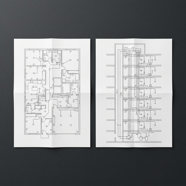
Shop drawings: floor plans, riser, point-to-point, and the math
Before installation, shop drawings tell the installer and the inspector exactly what will be built. The code lists what they contain: floor plans showing every device, control unit, annunciator and power supply with wiring routes; a riser diagram; a point-to-point wiring diagram for each circuit; the sequence of operation (input/output matrix); manufacturer data sheets for every listed component; secondary-power (battery) calculations; voltage-drop calculations for notification circuits; and the circuit class and survivability level of each pathway. A plan reviewer who can't find the battery calc hasn't been given a complete submittal.
NFPA 72 reference
Chapter 7 — Documentation
7.4 Shop Drawings (Installation Documents) — 7.4.1 through 7.4.9: floor plans, riser diagram, point-to-point, input/output matrix, product data sheets, battery calculations, voltage-drop calculations, pathway class/survivability
References use NFPA 72 2019/2022 numbering — section numbers can shift between editions, so confirm in the edition your AHJ has adopted.
On the job
A reviewer receives a floor plan and a one-line riser. No battery calc, no voltage drop, no I/O matrix. The submittal is returned as incomplete. When the full package arrives the voltage-drop calc shows the longest NAC ending at 15.2 V — below the strobes' 16 V minimum — so a NAC extender is added on paper instead of in the field after a failed acceptance test.
Quick check
1. Which item is NOT part of a Chapter 7 shop-drawing package?
2. A voltage-drop calculation proves that:
3. The sequence of operation is documented as a(n):
Listen to this section
AI-narrated, about a minute.
Ask about this section
Get a plain-language explanation of what this rule requires and what to check on the job.
3 free explanations left on this device.